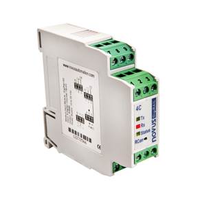
This guide will explain, step by step, how to add a Modbus Device in OnPing, using a Novus Digirail as an example Modbus Device.
Step 1: Connect RS-485 to USB to the Modbus Device
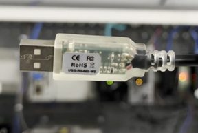
This particular converter has bare wires on one end and a USB plug on the other end. Exposed bare wire simplifies the connection to the screw terminals on the Novus Digirail (and other Modbus devices with screw terminals).
Step 2: Connect Modbus Device to the Lumberjack via USB
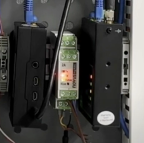
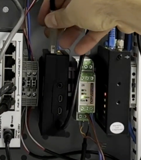
Once the wires are securely in the screw terminals, connect the USB plug end of the converter cord into any of the USB terminals on the Lumberjack. In this example, the USB cord is being plugged into one of the top USB ports.
Step 3: Install Modbus Driver onto the Lumberjack
After ensuring the Modbus Device, USB converter, and the Lumberjack are powered on and properly connected, install the Modbus Driver onto the Lumberjack. First, navigate to the desired Lumberjack for driver installation. To do this, navigate to the list of Lumberjacks. In this example, the Lumberjack list is located in the ‘Example Local HMI’ tab on the left.
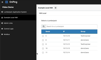
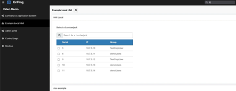
For this example, Lumberjack 9 will be used as the desired Lumberjack. To select Lumberjack 9, either click the checkbox next to Lumberjack 9 or, if a Lumberjack is not as easily accessible, type ‘ 9 ’ in the search engine at the top of the window to perform a quick search for Lumberjack 9.
If Lumberjack 9 does not simply appear after typing ‘ 9 ‘, try again while adding more parameters to the quick-search by typing ‘ 9 is:lumberjack ’ for a more specific search only for Lumberjacks.
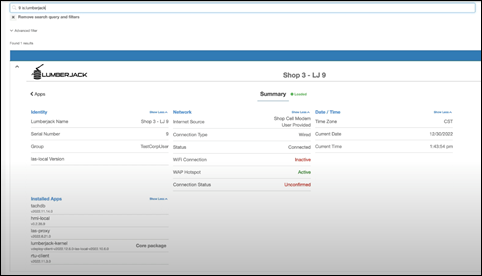
Once the Lumberjack summary screen is loaded, ensure that the Modbus Driver is installed under the ‘Installed Apps’ Column. To install the Modbus Driver, click ‘ Apps ’ at the top left corner of the Lumberjack summary screen.
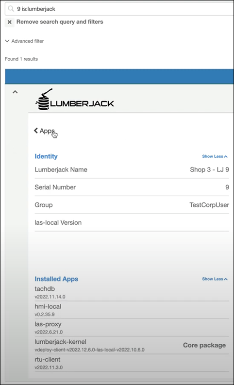
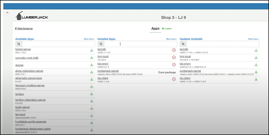
The Apps page will display applications available for the device, those currently installed on the device, and updates ready to be installed for current applications on the device. For this example, the Modbus Driver App is not installed on the Lumberjack because it is not displayed on the ‘Installed Apps’ list.
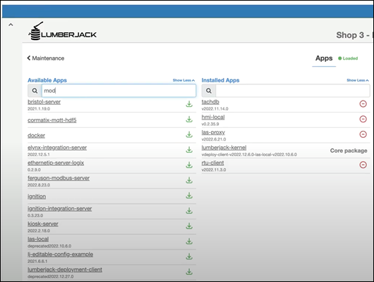
To install an app on the device, go to the search bar below ‘Available Apps’ and type ‘mod’ to find the ModBus Driver App.
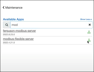
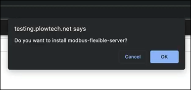
In the dropdown list, find ‘modbus-flexible-server’ and click the green down arrow to the right to download the application. An OnPing window in the internet browser may pop up to confirm that the driver installation is intentional. In this case, click OK to confirm the installation.
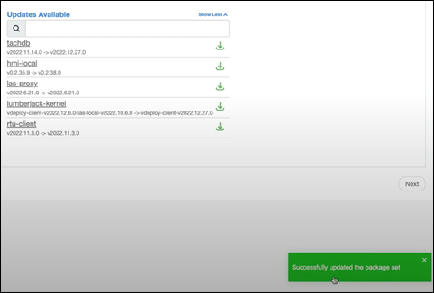
Once the driver is downloaded, a green pop-up will appear at the bottom right of the window, confirming that the download was successful and the package set has been updated.
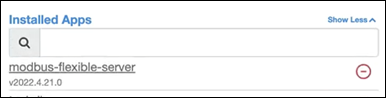
Ensure that the newly installed driver is displayed under the ‘ Installed Apps ‘ Column.
Step 4: Create and Assign Modbus Device Location
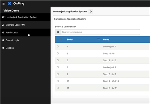
Navigate to the main menu to locate the Lumberjack. Click the ‘Admin Links’ tab on the left side of the window. If the ‘Admin Links’ tab is not displayed, please contact OnPing support or the system administrator for additional support.
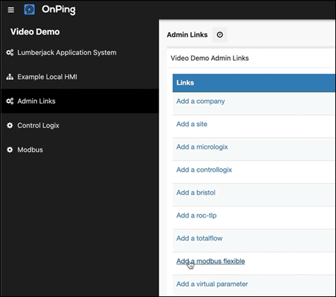
In ‘Admin Links’, select ‘Add a Modbus Flexible’. This will open the “coms screen”. In OnPing, the Communication and Configuration screens are always split into two separate screens.
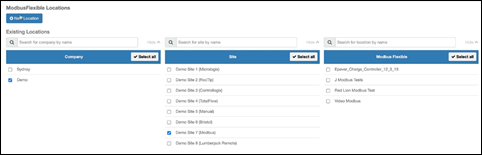
In this example, a new Location will be created for the ModBusFlexible Locations. Click ‘+ New Location’ to add a location.
A drop-down window will appear with fields to enter the location’s additional information.
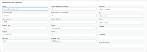
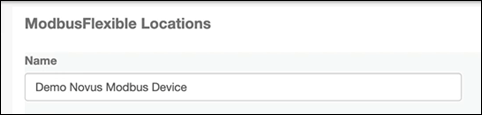
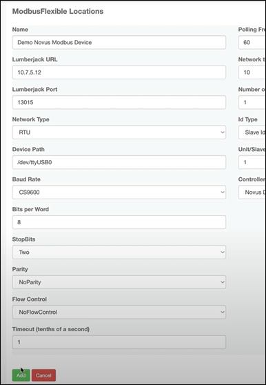
Name the Modbus Device. In this example, the name will be ‘Demo Novus Modbus Device’.
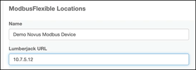
Next, enter the Lumberjack URL to connect to. This URL usually looks like a 10.x.x.x address. In this example, the URL entered for this specific Lumberjack is 10.7.5.12.
Note: In updated versions of OnPing, ‘Lumberjack URL’ will be replaced with ‘Lumberjack Serial’ to incorporate new data capture and acquisition technology.
The Lumberjack Port number field should already be populated and will not need to be changed. In this example, the port number is 13015.
Next, navigate down to ‘Network Type’ and select ‘RTU’ from the dropdown menu:
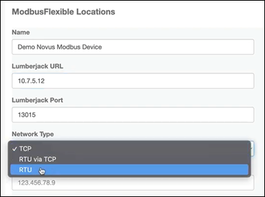
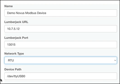
In this example, the device is reading serial data, so an RTU network type must be selected to import serial device data. This is the USB device plugged in during Steps 1 and 2. The path for the USB device will almost always be the same unless multiple USB devices are connected to the Lumberjack. In this example, the device path is: /dev/ttyUSB0
In this example, the Baud Rate is set to CS9600, and the Bits per Word is set to 8. For this particular device, the Stop Bits needs to be set to ‘Two’. Click the dropdown menu below ‘StopBits’ to change the setting from ‘One’ to ‘Two’.
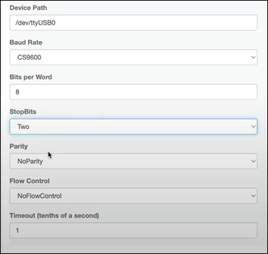
For Parity and Flow Control in this example, additional settings should be set to ‘NoParity’ and ‘NoFlowControl’, respectively. The timeout, in tenths of a second, should be set to 1.
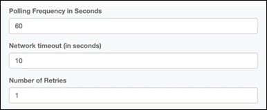
In the middle column, the Polling Frequency in Seconds is set to 60 seconds in this example. If the device does not respond within 10 seconds, the Lumberjack will retry once after 10 seconds.
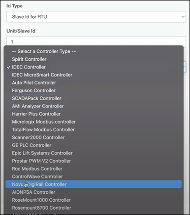
Change the Unit/Slave ID from ‘0’ to ‘1’. Next, select the controller type. If the controller type is unknown, the SCADApack Controller is an appropriate default. In this example, the controller type is known, so ‘Novus Digirail Controller’ is selected from the controller drop-down menu.
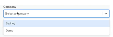
In the last column on the right side of the screen, select the Company this Location belongs to. In this example, Company ‘Demo’ is selected from the dropdown menu.
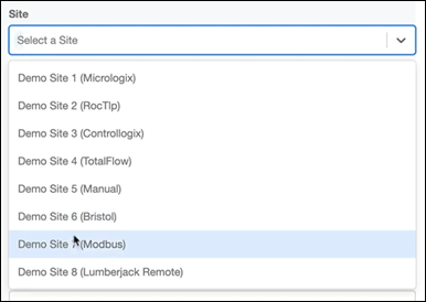
Next, select the site for the company. In this example, ‘Demo Site 7 (Modbus) is selected.
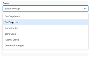
When selecting a group, the group with the lowest read-only permissions should be selected. In this example, ‘TestCorpUser’ is selected. Users in the ‘TestCorpUser’ group will have read-only permissions, while all users above that group will have read-write permissions.
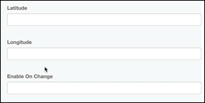
Latitude and longitude entries are not needed in this example, but they could be entered to store the device's location. Driving directions could then be generated from these coordinates.
Enable On Change will also not be needed in this example, but it is important to note that Enable On Change can save computational power by capturing data only when a value changes from its previous value within each capture interval.
Lastly, to save the location information, navigate to the bottom left corner of the Location screen and click the green button labeled ‘Add’
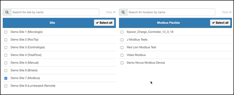
Now the ‘Demo Novus Modbus Device’ controller has been added to the controller list available for ‘Demo Site 7 (Modbus)’. To ensure it has been added correctly, click the checkbox next to the site name to ‘uncheck’ and then click the same box again to ‘check’. This will refresh the controllers list for that site.
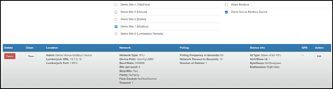
To ensure that all the information in the dropdown window entered earlier in this step is correct, select ‘Demo Novus Modbus Device’ from the controllers list to see a summary of the controller.
Step 5: Create Modbus Widget and Add to Panel
This step can be skipped if the Modbus Widget is already in the panel.
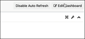
Navigate back to the main page by clicking the OnPing logo at the top left of the screen. To add a Modbus panel, the dashboard must be edited. Click ‘Edit Dashboard’ at the top right of the screen.
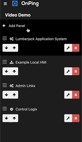
Once the Dashboard editor view is open, navigate to the top left of the screen to add a panel. Click ‘+ Add Panel’ under the dashboard name. In this example, the dashboard is named ‘Demo Video’.
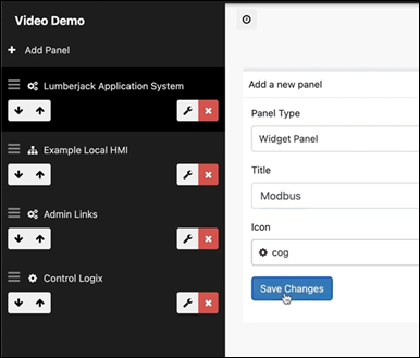
In this example, the panel will be a Widget Panel. Enter the panel title in the text bar under ‘Title’. For this example, the title will be ‘Modbus’. Next, select an icon for the panel. The ‘cog’ icon is selected for this panel. Lastly, click the blue button at the bottom of the window titled “Save Changes”.
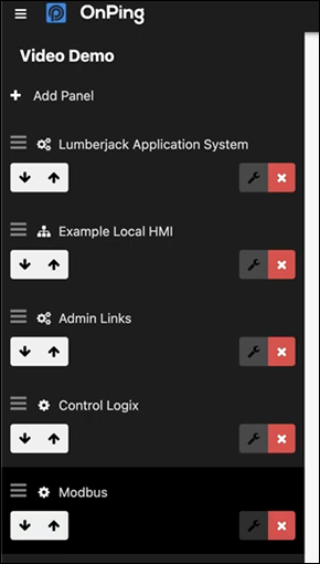
The dashboard will now be saved with the updated panels, including the newly created ‘Modbus’ panel.
The Modbus panel should now be selected. Navigate to the top right corner of the window and click the blue button titled ‘+ Widget’. For this particular example, the ‘Modbus Flexible’ widget will be added to the panel.
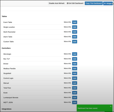
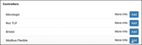
Now that the ‘Modbus Flexible’ Widget has been added to the panel, navigate to the top right corner of the screen and click the blue button titled ‘Save’. Then, after the save is complete, click the red button (to the left of the save button) titled ‘Cancel Edit Dashboard’ to exit dashboard edit mode.
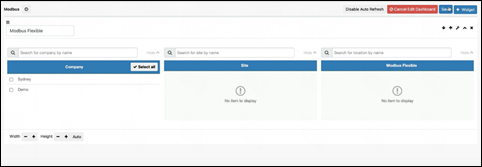
The Modbus Device has now been properly configured to import data into OnPing. Importing data and adding a Modbus Device to OnPing are straightforward processes that can be achieved by following the steps above.
Was this article helpful?
That’s Great!
Thank you for your feedback
Sorry! We couldn't be helpful
Thank you for your feedback
Feedback sent
We appreciate your effort and will try to fix the article